深度缓冲
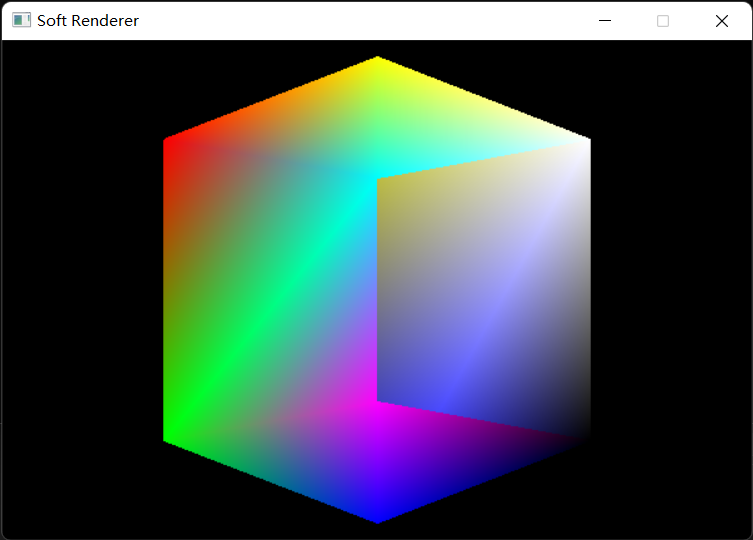
假如我们在场景中直接绘制一个立方体,那么它呈现出的样子会是这样的:
很显然,它并不符合正确的遮挡关系,而是后绘制出的会遮挡先绘制出的,为了实现正确的物体遮挡关系,也就是离摄像头近的遮挡离摄像头远的,我们需要一个深度缓冲区,也称作Z-Buffer。
原理:在每次绘制像素前将执行完透视除法后的z值与原本存储在Z-Buffer中同一位置的z值进行比较,如果小于(或等于)Z-Buffer中的z值,则深度测试通过,将新的z值写入,同时允许像素的绘制,反之不通过,像素被抛弃。
分配一块用于Z-Buffer的内存,并用于写入深度值及进行深度测试:
1
2
3
4
5
6
7
8
9
10
11
12
float * zBuffer = new float [width * height];for (int i = 0 ; i < width * height; i++) { zBuffer[i] = FLT_MAX; } bool DepthTest (int x, int y, float z) if (z <= zBuffer[y * width + x]) { zBuffer[y * width + x] = z; return true ; } return false ; }
在每次绘制像素前用插值得到的深度值进行深度测试,未通过就直接跳过绘制,注意如果像素位置在屏幕外就直接跳过,防止深度值写入到深度缓冲区外:
1
2
3
4
5
6
if (x >= width || x < 0 || y >= height || y < 0 ) continue ; float depth = mass.x * vertices[indices[0 ]].position.z + mass.y * vertices[indices[1 ]].position.z + mass.z * vertices[indices[2 ]].position.z;if (!DepthTest (x, y, depth)) continue ;
最终我们可以得到一个遮挡关系正确的立方体:
Z-Fighting
当深度测试开启时,离摄像机较远的片元会出现闪烁现象,这种现象被称为深度冲突(Z-Fighting)。我们最终写入深度缓冲区的深度值是经过透视投影变换后的,这会导致离摄像机近的物体深度值比离摄像机远的更精确,而如果两个物体离摄像机很远,而且靠得很近,那么深度测试就会产生误差,从而导致两个物体的片元出现Z-Fighting。
解决方案:
提高深度缓冲区的精度。
避免离摄像机很远的物体靠得太近。
适当地缩小近平面和远平面地距离。
采用Z值反转的算法(Reverse-Z),这时离摄像机远的物体深度值会更精确。
纹理映射
在上一节中我们研究了插值算法,插值的一个重要运用领域就是纹理映射,即通过uv坐标查找贴图中的像素值的过程,接下来我们就从简单的三角形开始出发,直到最后可以为整个模型贴上贴图。
首先我们要拥有一个高效的从外部加载图像的方法,虽然SDL本身提供了图像加载,但是由于我更熟悉扩展性更高的STB,所以这里还是选用STB,STB的使用方法也十分简单:
1 2 3 4 #define STB_IMAGE_IMPLEMENTATION #include "stb/stb_image.h"
构建一个Texture类来方便贴图的加载和采样:
1
2
3
4
5
6
7
8
9
10
11
12
13
14
15
16
17
18
19
20
21
22
23
24
class Texture { Texture () {} Texture (const char * path, uint32_t BPP) { LoadImageWithSTB (path, BPP); } void Release () stbi_image_free (source); } uint32_t width, height, BPP; uint64_t imageSize; stbi_uc* source; void LoadImageWithSTB (const char * path, uint32_t BPP) this ->BPP = BPP; int channelInFile; stbi_uc* source = stbi_load (path, reinterpret_cast <int *>(&width), reinterpret_cast <int *>(&height), &channelInFile, 4 ); uint64_t pixelRowPitch = ((uint64_t )width * (uint64_t )BPP + 7 ) / 8 ; imageSize = pixelRowPitch * (uint64_t )height; this ->source = reinterpret_cast <uint8_t *>(source); } }
BPP指Bit per pixel(每个像素的位数),如果是32位RGBA则BPP就是32,然后pixelRowPitch就可以用图像的宽度乘以BPP再向上取整得出,整个图像的内存大小就是pixelRowPitch乘以图像的高度。(我们默认认为图像的BPP是32)
在完成图像的加载之后,我们要做的就是根据uv坐标查找像素对应的颜色值,那么问题又来了,uv坐标的范围是[0,1]*[0,1]浮点数,而图像的大小是[0,width]*[0,height]整数,必然不可能为每一个像素都找到对应的颜色值,这个时候就只能采取近似的方法,在图形学中称作过滤(fillter),常用的过滤算法有最近邻过滤(Nearest neighbor filtering),双线性过滤(Bilinear filtering),三线性过滤(Trilinear filtering),双三次(立方)过滤(Bicubic filtering)和各向异性过滤(Anisotropic filtering)。
最近邻过滤
最近邻过滤的方法正如其名,对于一个无法与图像准确对应的uv坐标,只需要四舍五入找到距离其最近的颜色值,并把它设为我们想要的值即可,这种实现方法也相对比较简单。
原理:将所求uv坐标放进图像中,判断与其周围最近四个像素中心点的距离,最近的则为需要的像素。
代码:
1
2
3
4
5
6
7
8
9
10
11
12
13
14
15
16
17
18
19
20
21
22
23
Vector3f SampleNearest (float x, float y) { y = 1.0f - y; x = x * (float )this ->width; y = y * (float )this ->height; x -= 0.5f ; y -= 0.5f ; int width = x; int height = y; if (x - width > 0.5f )width++; if (x - height > 0.5f )height++; int byte = BPP / 32 ; Vector3f color; color.x = (float )source[height * this ->width * byte * 4 + width * 4 ] / 255.0f ; color.y = (float )source[height * this ->width * byte * 4 + width * 4 + 1 ] / 255.0f ; color.z = (float )source[height * this ->width * byte * 4 + width * 4 + 2 ] / 255.0f ; return color; }
双线性过滤
最近邻过滤虽然简单高效,但是在图像分辨率过低时会造成比较严重的锯齿现象,所以这时候选择效果更好且效率尚可的双线性过滤最佳。
原理:将所求uv坐标放进图像中,根据与其周围最近四个像素中心点的距离,先进行两次x轴上的插值,再进行一次y轴上的插值。
代码:
1
2
3
4
5
6
7
8
9
10
11
12
13
14
15
16
17
18
19
20
21
22
23
24
25
26
27
28
29
30
31
32
33
34
35
36
37
Vector3f SampleBilinear (float x, float y) { y = 1.0f - y; x = x * (float )this ->width; y = y * (float )this ->height; x -= 0.5f ; y -= 0.5f ; int width = x; int height = y; int byte = BPP / 32 ; Vector3f color[4 ]; for (int i = 0 ; i < 4 ; i++) { if (i == 1 && x > 0.0f && x < 9.0f ) width++; if (i == 2 && x > 0.0f && x < 9.0f ) width--; if (i == 3 && x > 0.0f && x < 9.0f ) width++; if (i == 2 && y > 0.0f && y < 9.0f ) height++; color[i].x = (float )source[height * this ->width * byte * 4 + width * 4 ] / 255.0f ; color[i].y = (float )source[height * this ->width * byte * 4 + width * 4 + 1 ] / 255.0f ; color[i].z = (float )source[height * this ->width * byte * 4 + width * 4 + 2 ] / 255.0f ; } float lerpX = (x - width) / 1.0f ; float lerpY = (y - height) / 1.0f ; color[0 ] = Lerp (color[0 ], color[1 ], lerpX); color[2 ] = Lerp (color[2 ], color[3 ], lerpX); return Lerp (color[0 ], color[2 ], lerpY); }
最终结果:
Mipmap和三线性过滤
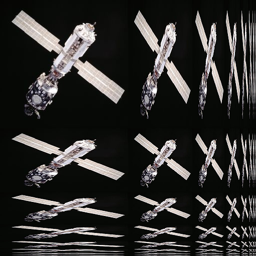
对于分辨率过小的图像,我们已经可以通过线性过滤的方法比较好的应对了,然而对于分辨率过大的图像,我们对它的采样频率远小于信号频率,这个时候通过常规的插值算法就无法解决,对此,图形学中引入了Mipmap的方法,该方法仅需要我们多耗费原存储空间的三分之一,就可以取得比较好的效果。
当然,想要使用Mipmap,首先我们得获得对应的图像,我们可以在程序外部提前准备好需要用的Mipmaps,或者是在程序内用类似双线性过滤或Box Filter的算法自动生成,这里我就直接准备好了要用的图像,不再费劲去想办法生成了。
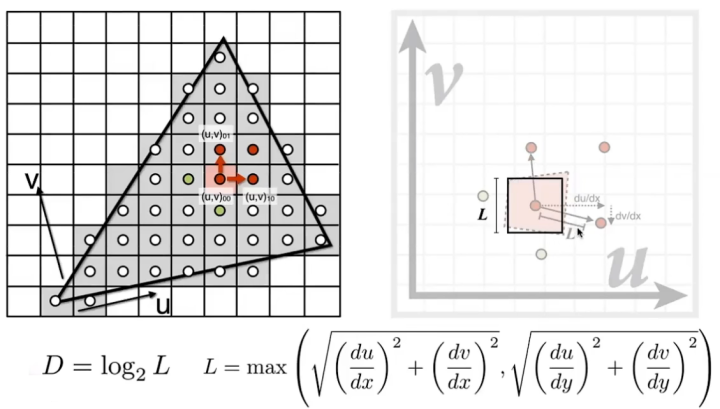
Mipmap level:一个像素会对应几个纹素,那么它就属于哪个Mip层级,比如Mipmap level 0就是一个像素对应一个纹素,Mipmap level 1就是一个像素对应四个纹素,由此可以推出,Mipmap level n就是一个像素对应 2 n 2^n 2 n
原理:假设原本对一个铺满屏幕的Quad进行纹理映射时,要使用的图像是最大的,即Mipmap level为0,当Quad逐渐远离摄像机,比如只占屏幕空间的四分之一时,此时需要使用二分之一分辨率的图像进行纹理映射,即Mipmap level为1。设在纹理空间中两个点的距离为L,我们所使用的Mipmap level可以用 D = log 2 L D=\log_2L D = log 2 L
代码:
1
2
3
4
5
6
7
8
9
10
11
12
13
14
15
16
17
18
19
20
21
22
23
24
25
26
27
28
29
30
31
32
33
34
35
36
37
38
39
40
41
42
43
44
45
46
47
float dx = 1.0f / width, dy = 1.0f / height;for (int y = minY; y <= maxY; y += 2 ) { for (int x = minX; x <= maxX; x += 2 ) { Vector3f mass[4 ]; Vector2f texCoord[4 ]; mass[0 ] = CalcBarycentric (x0, y0, x1, y1, x2, y2, x, y); mass[1 ] = CalcBarycentric (x0, y0, x1, y1, x2, y2, x + 1 , y); mass[2 ] = CalcBarycentric (x0, y0, x1, y1, x2, y2, x, y + 1 ); mass[3 ] = CalcBarycentric (x0, y0, x1, y1, x2, y2, x + 1 , y + 1 ); texCoord[0 ] = PerspectiveCorrectInterpolate (z[0 ], z[1 ], z[2 ], texCoord0, texCoord1, texCoord2, mass[0 ].y, mass[0 ].z); texCoord[1 ] = PerspectiveCorrectInterpolate (z[0 ], z[1 ], z[2 ], texCoord0, texCoord1, texCoord2, mass[1 ].y, mass[1 ].z); texCoord[2 ] = PerspectiveCorrectInterpolate (z[0 ], z[1 ], z[2 ], texCoord0, texCoord1, texCoord2, mass[2 ].y, mass[2 ].z); texCoord[3 ] = PerspectiveCorrectInterpolate (z[0 ], z[1 ], z[2 ], texCoord0, texCoord1, texCoord2, mass[3 ].y, mass[3 ].z); float Lx0 = powf (texCoord[0 ].x / dx - texCoord[1 ].x / dx, 2.0f ) + powf (texCoord[0 ].y / dy - texCoord[1 ].y / dy, 2.0f ); float Lx1 = powf (texCoord[2 ].x / dx - texCoord[3 ].x / dx, 2.0f ) + powf (texCoord[2 ].y / dy - texCoord[3 ].y / dy, 2.0f ); float Ly0 = powf (texCoord[0 ].x / dx - texCoord[2 ].x / dx, 2.0f ) + powf (texCoord[0 ].y / dy - texCoord[2 ].y / dy, 2.0f ); float Ly1 = powf (texCoord[1 ].x / dx - texCoord[3 ].x / dx, 2.0f ) + powf (texCoord[1 ].y / dy - texCoord[3 ].y / dy, 2.0f ); for (int i = 0 ; i < 4 ; i++) { if (!(mass[i].x > 0.0f && mass[i].y > 0.0f && mass[i].z > 0.0f ))continue ; if (x >= width || x < 0 || y >= height || y < 0 )continue ; float depth = mass[i].x * vertices[indices[0 ]].position.z + mass[i].y * vertices[indices[1 ]].position.z + mass[i].z * vertices[indices[2 ]].position.z; if (!DepthTest (i % 2 == 0 ? x : x + 1 , i < 2 ? y : y + 1 , depth))continue ; float L; switch (i) { case 0 : L = sqrtf (Lx0 > Ly0 ? Lx0 : Ly0); break ; case 1 : L = sqrtf (Lx0 > Ly1 ? Lx0 : Ly1); break ; case 2 : L = sqrtf (Lx1 > Ly0 ? Lx1 : Ly0); break ; case 3 : L = sqrtf (Lx1 > Ly1 ? Lx1 : Ly1); } int mipLevel = ceilf (logf (L)); mipLevel = mipLevel > maxMipLevel ? maxMipLevel : mipLevel; DrawPixel (renderer, i % 2 == 0 ? x : x + 1 , i < 2 ? y : y + 1 , texture[mipLevel].SampleBilinear (texCoord[i].x, texCoord[i].y)); } } }
在上面的代码中,我们直接采用clamp到最近mip层级的方法,但有的时候这样看起来会出现mipmap的突变,看起来效果并不好,可以采用在两个mip层级之间插值的方法解决这一问题,这就是三线性过滤。
修改原来的代码如下:
1
2
3
4
5
6
7
8
9
10
11
12
13
14
15
float mipLevel = logf (L);int mipLevel0 = mipLevel;Vector3f color; if (mipLevel - mipLevel0 != 0.0f ) { float percent = mipLevel - mipLevel0; Vector3f color0 = texture[mipLevel0].SampleBilinear (texCoord[i].x, texCoord[i].y); Vector3f color1 = texture[mipLevel0 + 1 ].SampleBilinear (texCoord[i].x, texCoord[i].y); color = Lerp (color0, color1, percent); } else color = texture[mipLevel0].SampleBilinear (texCoord[i].x, texCoord[i].y); mipLevel = mipLevel > maxMipLevel ? maxMipLevel : mipLevel; DrawPixel (renderer, i % 2 == 0 ? x : x + 1 , i < 2 ? y : y + 1 , color);
各向异性过滤
所谓各向异性,即在x方向和y方向上采取不同的缩放比例,这是为了解决一般的mipmap在正方形采样效果较好,但在面对宽高比差距较大时就会出现相对严重的瑕疵。因此,各项异性过滤可以在图像出现剧烈形变时给予mipmap更好的效果。
寻址模式
有的时候我们会遇到纹理坐标不在[0,1]*[0,1]范围内的情况,这个时候就要考虑将纹理坐标映射至能读取像素的范围内,这被称为纹理寻址模式(Texture-addressing mode)。
1
2
3
4
5
6
enum class AddressMode { Repeat = 0 , Mirror, Clamp, Border };
重复寻址模式(Repeat):
在纹理坐标的每个整数相接处重复纹理,这也是通常选择的一个模式:
1
2
3
4
5
6
while (coord > 1.0f ) { coord -= 1.0f ; } while (coord < 0.0f ) { coord += 1.0f ; }
镜像寻址模式(Mirror):
在每个整数边界对纹理做一次镜像:
1
2
3
4
5
6
7
8
9
10
11
bool mirror = false ;while (coord > 1.0f ) { coord -= 1.0f ; mirror = !mirror; } while (coord < 0.0f ) { coord += 1.0f ; mirror = !mirror; } if (mirror) coord = 1.0f - coord;
钳制寻址模式(Clamp):
将超出边界的纹理坐标钳制为边界坐标:
1
2
coord = coord > 1.0f ? 1.0f : coord; coord = coord < 0.0f ? 0.0f : coord;
边框寻址模式(Border):
将超出边界的纹理坐标设置为一个固定的边框颜色:
1
2
3
4
5
6
7
8
9
10
11
12
13
14
15
float TextureAddress (float coord, AddressMode addressMode) if (addressMode == AddressMode::Border) coord = coord > 1.0f || coord < 0.0f ? -1.0f : coord; return coord; } Vector3f SampleBilinear (float x, float y) { x = TextureAddress (x, AddressMode::Border); y = TextureAddress (y, AddressMode::Border); if (x == -1.0f || y == -1.0f ) return borderColor; ... }
绘制带贴图的模型
加载纹理贴图:
1
2
3
4
5
std::vector<Texture> textures (model.texturePath.size()) ;for (int i = 0 ; i < textures.size (); i++) { textures[i] = Texture (model.texturePath[i].c_str (), 32 ); textures[i].SetSampler (Texture::AddressMode::Border, Vector3f (0.0f , 0.0f , 0.0f )); }
加载顶点和索引:
1
2
3
4
5
6
7
8
std::vector<Vertex> vertices; std::vector<int > indices; for (auto & r : model.renderInfo) { for (auto & i : r.indices) indices.push_back (i + vertices.size ()); vertices.insert (vertices.end (), r.vertices.begin (), r.vertices.end ()); } pipeline.SetVertexBuffer (&vertices[0 ], vertices.size ());
设置MVP矩阵:
1
2
3
4
5
6
7
8
9
Camera camera ((float )width / (float )height) ;camera.SetLens (0.25f * M_PI, (float )width / height, 0.1f , 1000.0f ); camera.LookAt (Vector3f (0.0f , 0.0f , 1.0f ), Vector3f (0.0f , 0.0f , 0.0f ), Vector3f (0.0f , 1.0f , 0.0f )); camera.Walk (-15.0f ); camera.UpdataViewMatrix (); pipeline.SetWorldMatrix (Multiply (Multiply (Scale (1.0f , 1.0f , 1.0f ), RotateX (-M_PI * 0.5f )), Translate (0.0f , -15.0f , 0.0f ))); pipeline.SetViewMatrix (camera.GetViewMatrix4x4 ()); pipeline.SetProjectionMatrix (camera.GetProjMatrix4x4 ());
完成绘制:
1
2
3
4
5
6
7
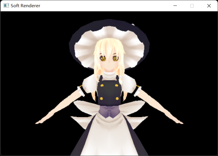
int baseOffset = 0 ;for (int i = 0 ; i < model.renderInfo.size (); i++) { for (int j = 0 ; j <= model.renderInfo[i].indices.size () - 3 ; j += 3 ) { pipeline.DrawTriangle (&indices[j + baseOffset], &textures[i]); } baseOffset += model.renderInfo[i].indices.size (); }
最终结果:
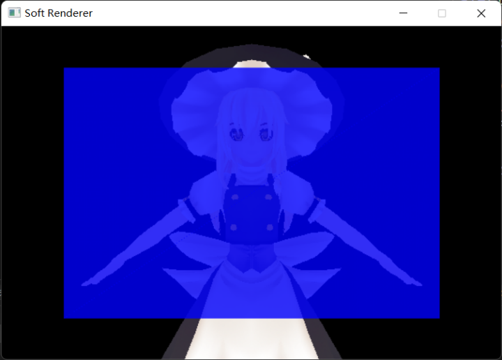
颜色混合
颜色混合允许我们在向帧缓冲写入像素时,决定写入像素和原像素的叠加关系,我们可以借此实现一些特殊效果(例如Billboard,透明效果)。为了实现颜色混合,我们需要向颜色向量中引入一个新的Alpha分量表示透明度,之后我们用到的所有颜色值都是包含四个分量的RGBA值。
动态分配一块用于存储颜色缓冲的内存,在绘制像素时先绘制到颜色缓冲上,而并非直接绘制到屏幕上:
1
2
3
4
5
6
7
8
9
10
11
12
13
14
15
16
17
18
19
20
21
22
23
24
25
26
27
28
Vector4f* frameBuffer = frameBuffer = new Vector4f[width * height]; for (int i = 0 ; i < width * height; i++) { frameBuffer[i] = Vector4f (0.0f , 0.0f , 0.0f , 0.0f ); } void Clear (Vector4f clearValue) for (int i = 0 ; i < width * height; i++) { frameBuffer[i] = clearValue; } } void Present () for (int i = 0 ; i < width * height; i++) { Vector4f color = frameBuffer[i]; SDL_SetRenderDrawColor (renderer, (Uint8)(color.x * 255 ), (Uint8)(color.y * 255 ), (Uint8)(color.z * 255 ), SDL_ALPHA_OPAQUE); SDL_Point point; point.x = i % width; point.y = i / width; SDL_RenderDrawPoints (renderer, &point, 1 ); } } void DrawPixel (SDL_Renderer* renderer, int x, int y, Vector4f color) SDL_Point point; point.x = x; point.y = y; frameBuffer[y * width + x] = color; }
修改DrawPixel的代码,使每当有新的颜色绘制到同一像素上时,执行混合方程:
1
2
3
4
5
color.x = color.x * color.w + frameBuffer[y * width + x].x * (1.0f - color.w); color.y = color.y * color.w + frameBuffer[y * width + x].y * (1.0f - color.w); color.z = color.z * color.w + frameBuffer[y * width + x].z * (1.0f - color.w); color.w = 1.0f ; frameBuffer[y * width + x] = color;
最终结果:
光照
法向量
为了完成后续的光照计算,我们需要准备好光源信息,摄像机信息以及物体的表面法线,前两个都好说,唯有法线是一个棘手的难题,想要得到正确的法向量需要先坐标变换再进行插值。
我们需要将法向量从物体空间变换至世界空间中(和光源处于同一空间),对于物体表面切线 t ⃗ \vec{t} t M M M
t ′ ⃗ = t ⃗ M \vec{t'}=\vec{t}M\\
t ′ = t M
由法向量和切向量的垂直关系得:
n ⃗ ⋅ t ⃗ = 0 ⃗ n ′ ⃗ ⋅ t ′ ⃗ = 0 ⃗ \vec{n}\cdot\vec{t}=\vec{0}\\
\vec{n'}\cdot\vec{t'}=\vec{0}\\
n ⋅ t = 0 n ′ ⋅ t ′ = 0
代入前式得:
n ′ ⃗ ⋅ t ⃗ M = 0 ⃗ \vec{n'}\cdot\vec{t}M=\vec{0}\\
n ′ ⋅ t M = 0
假设法线的变换矩阵为 N N N
n ′ ⃗ = n ⃗ N \vec{n'}=\vec{n}N\\
n ′ = n N
结合前式得:
n ⃗ N ⋅ t ⃗ M = 0 ⃗ n ⃗ N M T t ⃗ T = 0 ⃗ \vec{n}N\cdot\vec{t}M=\vec{0}\\
\vec{n}NM^T\vec{t}^T=\vec{0}\\
n N ⋅ t M = 0 n N M T t T = 0
又由于 n ⃗ ⋅ t ⃗ T = 0 ⃗ \vec{n}\cdot\vec{t}^T=\vec{0} n ⋅ t T = 0
N = ( M − 1 ) T N=(M^{-1})^T\\
N = ( M − 1 ) T
所以,我们需要的法向量变换矩阵即为世界矩阵的逆转置矩阵。
法向量变换矩阵的性质:
当世界矩阵仅为平移,旋转,等比例缩放的结合时,世界矩阵是正交矩阵,又因为正交矩阵的逆矩阵即转置矩阵,所以该情况下法向量变换矩阵就是世界矩阵。
当世界矩阵不可逆时,可以考虑用伴随矩阵取代逆矩阵进行计算,最后再进行归一化处理。
Blinn-Phong光照模型
Blinn-Phong光照模型是一个很好的基于光栅化的真实感局部光照模拟方法,在这个模型中,物体的光照着色被划分成了三部分:环境光(Ambient light),漫反射(Diffuse reflection)和镜面反射(Specular reflection),计算Blinn-Phong光照的过程就是将这三个部分的光照算出来最后完成叠加,形成物体最后的颜色。
漫反射:
所谓漫反射,就是从物体表面反射出去的光线从各个角度都可以接收到,因此,漫反射颜色并不会受到我们观察的影响,而是只与光源和物体有关。
计算漫反射我们需要考虑物体能够接收到多少光源发出的光,即单位面积上的辐射通量,这一点很好理解,假如一个平面正对着光源,那么它所能接收到的光照肯定是最多的,相反,如果一个平面测对着光源,那么它所能接收的光源就会相对减少。我们有一个方法可以计算平面接收到的光照的量,即兰伯特余弦定理(Lambert’s cosine law):
cos θ = l ⃗ ⋅ n ⃗ \cos\theta=\vec{l} \cdot \vec{n}\\
cos θ = l ⋅ n
我们需要光线向量和完成变换和插值后的法向量来进行计算:
1
2
float lambertFactor = max (Dot (normal, light.direction), 0.0f );Vector3f lightStrength = lambertFactor * light.strength;
镜面反射:
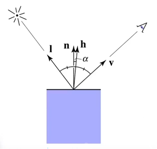
镜面反射同时受光源和观察方向影响,通常我们认为假如一条入射光线相对于法线的反射光线正好射向眼睛里,那么就可以看到最强的镜面反射,假如反射光线偏离眼镜越远,那么镜面反射就越弱。为了简化运算,我们可以先由光线向量和观察向量计算出一个半角向量(用单位向量计算),接着将半角向量与表面法线进行比较,若越接近则镜面反射越强:
h = n o r m a l i z e ( l ⃗ + v ⃗ ) c o s α = n ⃗ ⋅ h ⃗ h=normalize(\vec{l}+\vec{v}) \\cos\alpha=\vec{n}\cdot \vec{h}\\
h = n or ma l i ze ( l + v ) cos α = n ⋅ h
为了控制镜面反射的强度,我们额外规定一个shininess参数作为 cos α \cos\alpha cos α cos s h i n i n e s s α \cos^{shininess}\alpha cos s hinin ess α
代码:
1
2
3
Vector3f halfVec = (normal + light.direction).Normalize (); float cosAlpha = max (Dot (halfVec, normal), 0.0f );float specularAlbedo = pow (cosAlpha, material.shininess);
环境光:
在局部光照中,我们对环境光的考虑相对来说较为简单,是一个常量光照,并且与任何光源和物体无关,直接叠加到物体的光照颜色上。
代码:
1 Vector3f albedo = ambientLight + lambertFactor * light.strength + specularAlbedo * light.strength;
光源
方向光源:
方向光是由无数条朝向单一方向的光线组成的,且不会发生衰减,通常用来模拟自然环境下的日光。方向光的结构定义很简单且不需要做多余的处理,只需要用兰伯特余弦定理降低光强。
代码:
1
2
3
4
5
6
7
8
9
10
struct Light { Vector3f strength; Vector3f direction; }light; ... Vector3f lightVec = -light.direction; float lambertFactor = max (dot (lightVec, normal), 0.0f );Vector3f lightStrength = light.strength * lambertFactor;
点光源:
点光源比方向光源要多注意的一点就是,点光源的光照强度会随着距离变远而发生衰减,在越远的地方点光源就越不容易波及,而这种衰减满足平方反比规律,即 E = I R 2 E=\frac{I}{R^2} E = R 2 I
代码:
1
2
3
4
5
6
7
8
9
10
11
12
struct Light { Vector3f strength; Vector3f direction; Vector3f position; }light; ... Vector3f lightVec = light.position - eyePos; float lambertFactor = max (dot (lightVec, normal), 0.0f );float distance = sqrt (lightVec.x * lightVec.x + lightVec.y * lightVec.y + lightVec.z * lightVec.z);Vector3f lightStrength = lambertFactor * light.strength / (distance * distance);
聚光灯光源:
聚光灯除了距离衰减以外,还有额外的半径衰减,即离聚光灯照射中心越远,能接收到的光照也就越少:
代码:
1
2
3
4
5
6
7
8
9
10
11
12
13
14
struct Light { Vector3f strength; Vector3f direction; Vector3f position; float spotPower; }light; ... Vector3f lightVec = light.position - eyePos; float lambertFactor = max (dot (lightVec, normal), 0.0f );float spotFactor = max (Dot (-lightVec, light.direction), 0.0f );spotFactor = pow (spotFactor, light.spotPower); lightStrength = spotFactor * lambertFactor * lightStrength;
材质与BRDF
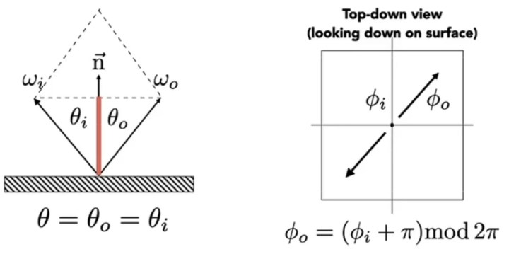
BRDF(Bidirectional reflectance distribution function,双向反射分布函数) 规定了对于一个特定材质的平面,它的入射光和反射光之间的关系,也就是说通过描述BRDF就可以做到描述不同的物体材质。
对于BRDF,我们有以下用于描述材质属性的结构体:
1
2
3
4
5
struct Material { Vector3f diffuseAlbedo; Vector3f fresnelR0; float shiniess; };
菲涅耳方程(Fresnel Equations):
当光线碰撞到一个平面时,一部分光线会折射进去,另一部分会反射出去,折射和反射满足能量守恒定律,假如 R f R_f R f 1 − R f 1-R_f 1 − R f 石里克近似法(Schlick approximation) :
R f ( θ i ) = R f ( 0 ∘ ) + ( 1 − R f ( 0 ∘ ) ) ( 1 − c o s θ i ) 5 R_f(\theta_i)=R_f(0^\circ)+(1-R_f(0^\circ))(1-cos\theta_i)^5\\
R f ( θ i ) = R f ( 0 ∘ ) + ( 1 − R f ( 0 ∘ )) ( 1 − cos θ i ) 5
其中 R f ( 0 ∘ ) R_f(0^\circ) R f ( 0 ∘ ) R f ( 0 ∘ ) R_f(0^\circ) R f ( 0 ∘ )
微表面模型(Microfacet Theory):
微表面模型描述了这样一件事:我们的平面实际上并不是真的“平面”,而是由无数微小的凹凸不平的表面组成的,而所谓的漫反射也就是在这样无数的微表面上形成的,随着粗糙程度的增大,微表面法线会越来越偏离宏观表面法线,所谓镜面反射,实际上就是微表面法线和宏观表面法线接近达到一定程度。
S ( θ h ) = m + 8 8 ( n ⃗ ⋅ h ⃗ ) m S(\theta_h)=\frac{m+8}{8}(\vec{n}\cdot\vec{h})^m\\
S ( θ h ) = 8 m + 8 ( n ⋅ h ) m
我们可以将前文叙述的镜面反射计算公式与某种归一化因子结合,得到以下公式:m m m
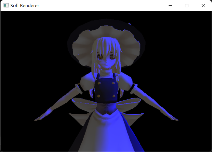
最终的光照模型:
1 2 3 4 5 6 7 8 9 10 11 12 13 14 15 16 17 18 19 20 21 22 23 24 const float shininess = material.shininess * 256.0f ;Vector3f halfVec = (normal + light.direction).Normalize (); float roughnessFactor = (shininess + 8.0f ) * pow (max (Dot (halfVec, normal), 0.0f ), shininess) / 8.0f ;float cosIncidentAngle = saturate (Dot (normal, lightVec));float f0 = 1.0f - cosIncidentAngle;Vector3f reflectPercent = material.fresnelR0 + pow (f0, 5 ) * (Vector3f (1.0f ) - material.fresnelR0); Vector3f specularAlbedo = roughnessFactor * reflectPercent; Vector3f lightingResult = (material.diffuseAlbedo + specularAlbedo) * lightStrength; Vector4f litColor = Vector4f ((ambientLight + lightingResult), 1.0f ) * diffuse; litColor.x = saturate (litColor.x); litColor.y = saturate (litColor.y); litColor.z = saturate (litColor.z); return litColor;
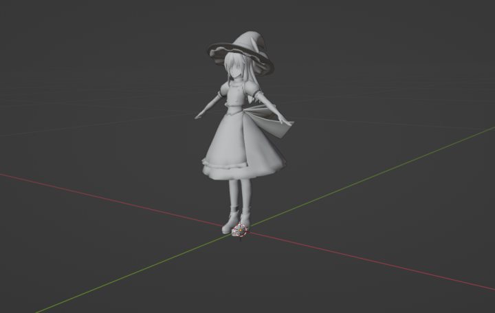
最终结果:
绕序和背面剔除
背面剔除时一种常规的绘制优化手段,根据顶点的绕序,我们可以规定一个三角形平面是正面还是背面,并把不需要的面剔除,举个例子,我们在右手坐标系中一般把逆时针绕序规定为正面,顺时针绕序规定为背面,绕序会由我们的观察方向决定,那么同样一个平面是正面还是背面就也可以由我们的观察方向决定。
可以使用叉积在绘制三角形时实现对绕序的判断:
1
2
3
4
5
6
7
8
bool CullFace (Vector2i v0, Vector2i v1, Vector2i v2) Vector3f v01 = Vector3f (v1.x - v0.x, v1.y - v0.y, 0.0f ); Vector3f v02 = Vector3f (v2.x - v0.x, v2.y - v0.y, 0.0f ); Vector3f cross = Cross (v01, v02); if (cross.z > 0.0f ) return false ; return true ; }
反走样(MSAA)
走样的原因:用有限的采样点去逼近连续的图像,然而图像信号的频率大于采样的频率,导致采样不完全,因此出现锯齿状瑕疵,这就被称为走样(Aliasing) 。
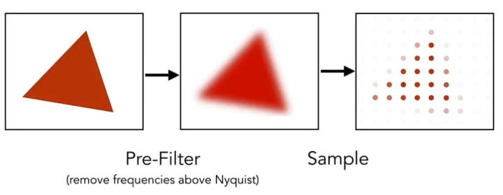
信号处理层面的反走样方法:对图像进行卷积操作,使其模糊化,减少高频信号点,之后再进行采样就可得到相对平滑的图形边缘。
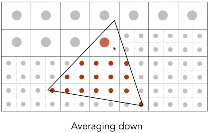
图形学上的反走样方法:将原本的屏幕像素细分为更小的像素,并用这些更小的像素去对图形进行采样,这样采样点的数量就得以增加,然后计算图形在一个像素中的覆盖率,并借此得到颜色的灰度值,若完全覆盖则灰度值最高,若不覆盖则灰度值为0,这种方法就被称为超级采样反走样(Super Sampling Anti-Aliasing,SSAA) 。
但是SSAA的最大缺点就是由于我们对每个增加的采样点都要执行一次片元着色计算,所以会造成成倍的开销,因此在实际运用时我们会使用一个近似做法,被称为多重采样反走样(Muti-Sampling Anti-Aliasing,MSAA) 。
MSAA原理:MSAA与SSAA的思想相同,每一个像素都会有多个采样点,存储不同颜色,但并不会为每个采样点都进行一次片元着色计算,而是只为图形最先遮挡到的采样点进行计算。
将颜色和深度缓冲区改为屏幕大小的多重采样倍数,以便在MSAA为多余的采样点分别存储颜色和深度:
1
2
3
4
5
6
7
8
9
10
11
12
13
14
15
16
17
18
19
zBuffer = new float [width * height * sampleCount]; frameBuffer = new Vector4f[width * height * sampleCount]; bool DepthTest (int x, int y, int samplePoint, float z) if (z <= zBuffer[samplePoint * width * height + y * width + x]) { zBuffer[samplePoint * width * height + y * width + x] = z; return true ; } return false ; } void DrawPixel (SDL_Renderer* renderer, int x, int y, int samplePoint, Vector4f color) int index = samplePoint * width * height + y * width + x; color.x = color.x * color.w + frameBuffer[index].x * (1.0f - color.w); color.y = color.y * color.w + frameBuffer[index].y * (1.0f - color.w); color.z = color.z * color.w + frameBuffer[index].z * (1.0f - color.w); color.w = 1.0f ; frameBuffer[index] = color; }
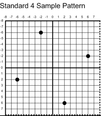
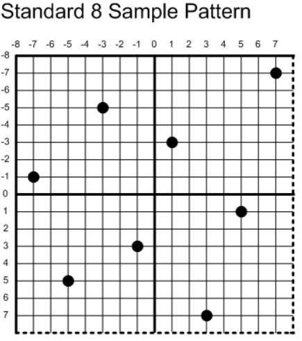
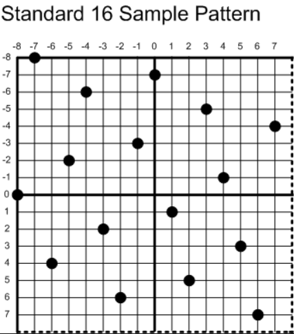
我在绘制三角形的循环内部为每个多余的采样点计算各自的坐标,对于不同倍数的MSAA,它的采样点坐标遵循以下原则(标准采样点来自DirectX):
这样做的好处是使采样点得均匀的分配,最终MSAA出来的效果会更好,我以4xMSAA为例,在原来绘制三角形的算法中添加计算采样点坐标的步骤,代码如下:
1
2
3
4
5
6
7
8
9
10
11
12
13
14
15
16
17
18
19
20
21
22
23
24
25
26
float offset[2 ] = { 1.0f / 16.0f * 6.0f , 1.0f / 16.0f * 2.0f };Vector2f position[4 ]; position[0 ] = Vector2f (x - offset[1 ], y + offset[0 ]); position[1 ] = Vector2f (x + offset[0 ], y + offset[1 ]); position[2 ] = Vector2f (x - offset[0 ], y - offset[1 ]); position[3 ] = Vector2f (x + offset[1 ], y - offset[0 ]); Vector4f finalColor; bool detected = false ;for (int i = 0 ; i < 4 ; i++) { Vector3f mass = CalcBarycentric (x0, y0, x1, y1, x2, y2, position[i].x, position[i].y); if (mass.x >= -1e-5 f && mass.y >= -1e-5 f && mass.z >= -1e-5 f) { float depth = mass.x * vertices[indices[0 ]].position.z + mass.y * vertices[indices[1 ]].position.z + mass.z * vertices[indices[2 ]].position.z; if (!DepthTest (x, y, i, depth)) continue ; if (!detected) { Vector2f texCoord = PerspectiveCorrectInterpolate (z[0 ], z[1 ], z[2 ], texCoord0, texCoord1, texCoord2, mass.y, mass.z); Vector3f normal = PerspectiveCorrectInterpolate (z[0 ], z[1 ], z[2 ], vertices[indices[0 ]].normal, vertices[indices[1 ]].normal, vertices[indices[2 ]].normal, mass.y, mass.z); finalColor = FragmentShading (texture->SampleBilinear (texCoord.x, texCoord.y), normal); detected = true ; } DrawPixel (renderer, x, y, i, finalColor); } }
在最终将颜色缓冲转化成像素绘制到屏幕时,为每个像素的采样点所拥有的颜色做一个加权平均,方可得出像素的最终颜色:
1
2
3
4
5
6
7
8
9
10
11
12
13
14
15
16
17
18
19
20
for (int i = 0 ; i < width * height; i++) { Vector4f color; color.x = frameBuffer[i].x * 0.25f + frameBuffer[width * height + i].x * 0.25f + frameBuffer[width * height * 2 + i].x * 0.25f + frameBuffer[width * height * 3 + i].x * 0.25f ; color.y = frameBuffer[i].y * 0.25f + frameBuffer[width * height + i].y * 0.25f + frameBuffer[width * height * 2 + i].y * 0.25f + frameBuffer[width * height * 3 + i].y * 0.25f ; color.z = frameBuffer[i].z * 0.25f + frameBuffer[width * height + i].z * 0.25f + frameBuffer[width * height * 2 + i].z * 0.25f + frameBuffer[width * height * 3 + i].z * 0.25f ; SDL_SetRenderDrawColor (renderer, (Uint8)(color.x * 255 ), (Uint8)(color.y * 255 ), (Uint8)(color.z * 255 ), SDL_ALPHA_OPAQUE); SDL_Point point; point.x = i % width; point.y = i / width; SDL_RenderDrawPoints (renderer, &point, 1 ); }
最终结果:
前后对比,可以看出,仅仅使用4xMSAA就可以让锯齿瑕疵显著地减少。
